![]()
![]()
|
|
|
|
Grade Control at Eden Hill
Asset Construction, LLC utilizes Trimble's GPS RTK (Real Time Kinematics) Technologies to establish Grade Control at the Eden Hill Medical Center site. Our Site Positioning System gives our foremen, supervisors, grade checkers and site engineers the tools they need to help run machines on site, reduce downtime and resolve issues as they arise-without office assistance. The system consists of several elements. They are:
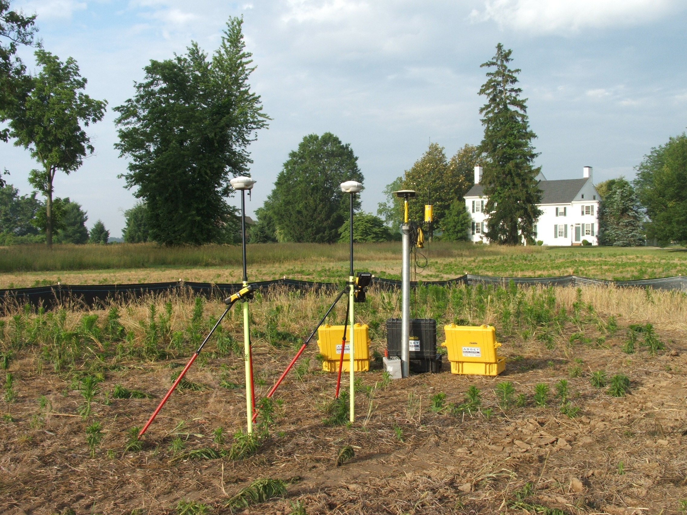
1. A GPS Base Station broadcasting location corrections to the receivers operating on the site. The Base Station is set up over a known point and remains stationary during daily operations. For quick setups, the base station can be set up on a tripod. For sites where we will be working for a longer period of time, the base station can be set up on or in a site trailer or other permanent fixture. To avoid any movement of our Base Station, Asset Construction, LLC uses a 3" iron pipe driven six foot into the ground on our large sites.
2. Tri-pod Mounted Bluetooth equipped Rovers. The rover element consists of a GPS receiver, a receive radio, and a controller with a software application. These components can be set up on a rover rod, ATV, supervisor’s vehicle, or other mobile asset. GPS signals experience interference as they pass through the earth’s atmosphere. These signals originate from satellites orbiting the earth, and are received by GPS receivers on the earth’s surface. The atmosphere can distort the different GPS signals resulting in “signal noise.” Therefore, the base station must be set up over a known point on the job site. The base station takes the location information it receives from the satellites overhead, compares it to its current, known coordinate, and computes a correction.
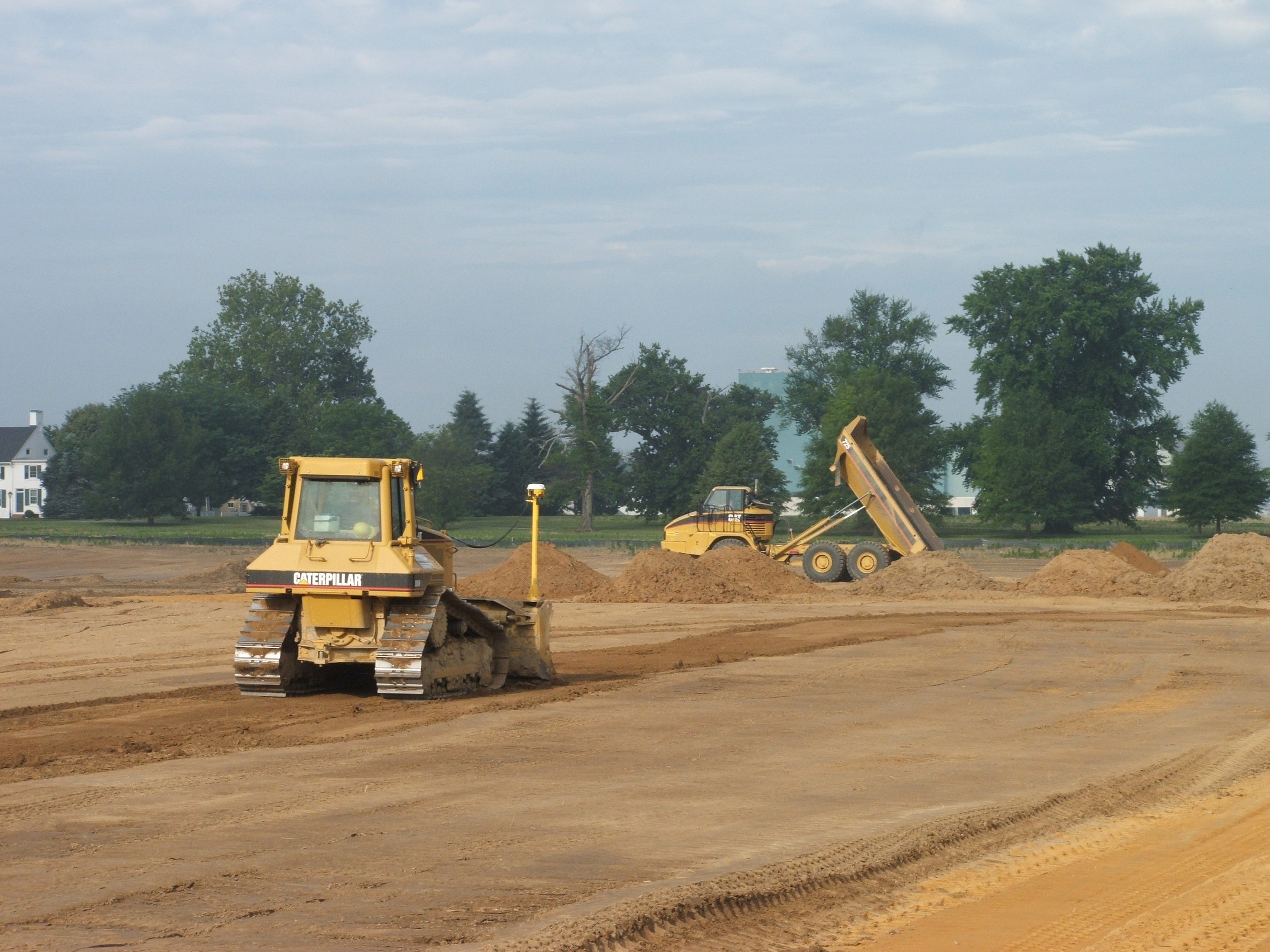
3. GPS equipped Caterpillar D6N capable of automatic Blade control. The positioning sensors are used to compute exact position of the blade or bucket many times per second. The on-board computer uses this position information, and compares it to the design elevation to compute cut or fill to grade. This information displays on the SV170 screen— in plan, profile, cross-section view, or text. The cut/fill data is also used to drive the valves for automatic blade control. Additionally, the cut/fill data is passed to the GCS900 light bars, providing additional visual guidance to the operator for up/down to grade and right/left to a defined alignment. The light bars are separate from the display so that the operator can focus on safely operating the machine by having the light bar in the field of view.
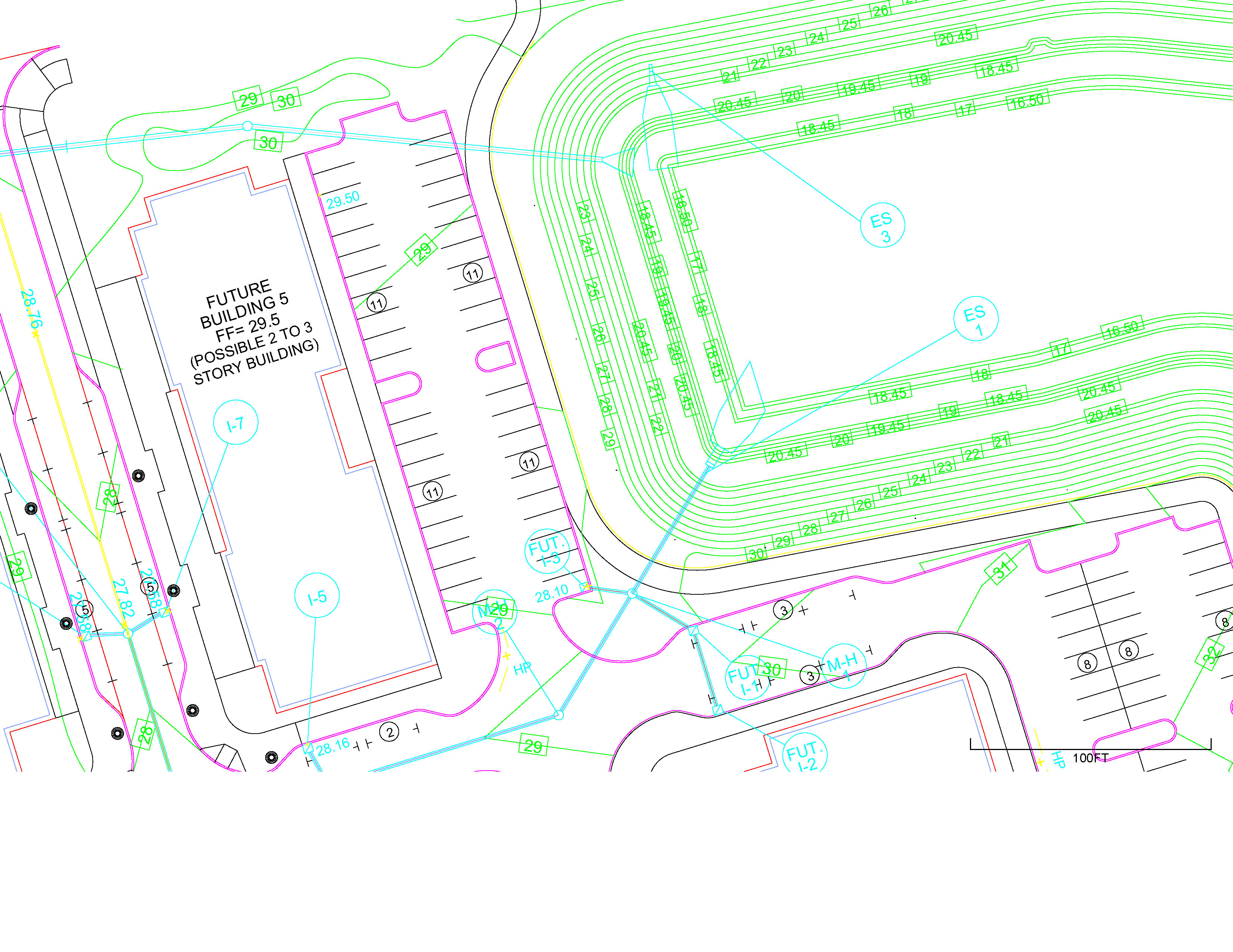
4. A 3D computer model of the site incorporating the physical location of the various structures and features to be constructed on the site. Shown to the right is a portion of the location model which shows a portion of the retention pond, a future building and a portion of of a roadway. The image can be enlarged to see greater detail.
5. Another computer model comprising the grading plan for the site, i.e. the finished grade of the parking lots, culverts and other drainage structure. Shown to the left is the same area as above.
A composite image of the Retention Pond as seen by the processors in the Controllers can be seen to the left. When all these elements are combined, the site can be brought to grade and all the structures installed in a stake-less environment. The efficiencies and cost saving for both the contractor and the client are obvious. The excavation crews have the finished grade for any point on the site at their fingertips at all times. No waiting for a survey crew to come to the site and stake out an area or replace a hub knocked out in the course of construction. When properly calibrated and operated the accuracy of the system is measured in centimeters. How Does it Work? The roving GPS receiver also receives information from the same satellites orbiting the earth. However, the rover does not have one fixed location so it cannot compute its own corrections. This is where the base station is needed. Through its transmit radio, the base station sends the corrections it computed to the roving GPS receiver which receives the corrections through its receive radio. The roving receiver uses the correction calculation from the base station and is able to determine its horizontal and vertical location. One base station can support multiple roving assets on a job site.
|